Four Stroke Engine

11:04 am / Posted by tech data / comments (0)

Today, internal combustion engines in cars, trucks, motorcycles, aircraft, construction machinery and many others, most commonly use a four-stroke cycle. The four strokes refer to intake, compression, combustion (power) and exhaust strokes that occur during two crankshaft rotations per working cycle of the Gasoline engine and Diesel engine.


A four-stroke engine is characterized by four strokes, or reciprocating movements of a piston in a cylinder:

  1. intake (induction) stroke
  2. compression stroke
  3. power stroke
  4. exhaust stroke

In this example animation, the right blue side is the intake and the left yellow side is the exhaust. The cylinder wall is a thin sleeve surrounded by cooling water.

The cycle begins at top dead center (TDC), when the piston is farthest away from the axis of the crankshaft. On the intake or induction stroke of the piston, the piston descends from the top of the cylinder, reducing the pressure inside the cylinder. A mixture of fuel and air is forced (by atmospheric or greater pressure) into the cylinder through the intake (inlet) port. The intake (inlet) valve (or valves) then close(s), and the compression stroke compresses the fuel–air mixture.

The air–fuel mixture is then ignited near the end of the compression stroke, usually by a spark plug (for a gasoline or Otto cycle engine) or by the heat and pressure of compression (for a Diesel cycle or compression ignition engine). The resulting pressure of burning gases pushes the piston through the power stroke. In the exhaust stroke, the piston pushes the products of combustion from the cylinder through an exhaust valve or valves.

Carnot Cycle

10:41 pm / Posted by tech data / comments (0)

The Carnot cycle is a particular thermodynamic cycle, modeled on the hypothetical Carnot heat engine, proposed by Nicolas Léonard Sadi Carnot in 1824 and expanded upon by Benoit Paul Émile Clapeyron in the 1830s and 40s.

A heat engine acts by transferring energy from a warm region to a cool region of space and, in the process, converting some of that energy to mechanical work. The cycle may also be reversed. The system may be worked upon by an external force, and in the process, it can transfer thermal energy from a cooler system to a warmer one, thereby acting as a heat pump rather than a heat engine.

The Carnot cycle is the most efficient cycle possible for converting a given amount of thermal energy into work or, conversely, for using a given amount of work for refrigeration purposes.

The Carnot cycle

The Carnot cycle when acting as a heat engine consists of the following steps:

  1. Reversible isothermal expansion of the gas at the "hot" temperature, TH (isothermal heat addition). During this step (A to B on Figure 1, 1 to 2 in Figure 2) the expanding gas causes the piston to do work on the surroundings. The gas expansion is propelled by absorption of quantity Q1 of heat from the high temperature reservoir.
  2. Isentropic (Reversible adiabatic) expansion of the gas. For this step (B to C on Figure 1, 2 to 3 in Figure 2) we assume the piston and cylinder are thermally insulated, so that no heat is gained or lost. The gas continues to expand, doing work on the surroundings. The gas expansion causes it to cool to the "cold" temperature, TC.
  3. Reversible isothermal compression of the gas at the "cold" temperature, TC. (isothermal heat rejection) (C to D on Figure 1, 3 to 4 on Figure 2) Now the surroundings do work on the gas, causing quantity Q2 of heat to flow out of the gas to the low temperature reservoir.
  4. Isentropic compression of the gas. (D to A on Figure 1, 4 to 1 in Figure 2) Once again we assume the piston and cylinder are thermally insulated. During this step, the surroundings do work on the gas, compressing it and causing the temperature to rise to TH. At this point the gas is in the same state as at the start of step 1.
Figure 1: A Carnot cycle acting as a heat engine, illustrated on a temperature-entropy diagram. The cycle takes place between a hot reservoir at temperature TH and a cold reservoir at temperature TC. The vertical axis is temperature, the horizontal axis is entropy.
Figure 2: A Carnot cycle acting as a heat engine, illustrated on a pressure-volume diagram to illustrate the work done.

Diesel Cycle

10:08 pm / Posted by tech data / comments (0)

The Diesel cycle is the thermodynamic cycle which approximates the pressure and volume of the combustion chamber of the Diesel engine, invented by Rudolph Diesel in 1897. It is assumed to have constant pressure during the first part of the "combustion" phase , v2 to v3 in the diagram .

Maximum thermal efficiency

The maximum thermal efficiency of a diesel cycle is dependent on the compression ratio and the cut-off ratio. It has the following formula:

\eta_{th}=1-\frac{1}{r^{\gamma-1}}\left ( \frac{\alpha^{\gamma}-1}{\gamma(\alpha-1)} \right )


Where

ηth is thermal efficiency
α is the cut-off ratio \frac{V_3}{V_2} (ratio between the end and start volume for the combustion phase)
r is the compression ratio \frac{V_1}{V_2}
γ is ratio of specific heats (Cp/Cv)


The cut-off ratio can be expressed in terms of temperature as shown below:

\frac{T_2}{T_1} ={\left(\frac{V_1}{V_2}\right)^{\gamma-1}} = r^{\gamma-1}


 \displaystyle {T_2} ={T_1} r^{\gamma-1}


\frac{V_3}{V_2}  = \frac{T_3}{T_2}


\alpha = \left(\frac{T_3}{T_1}\right)\left(\frac{1}{r^{\gamma-1}}\right)

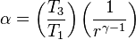
T3 can be approximated to the flame temperature of the fuel used. The flame temperature can be approximated to the adiabatic flame temperature of the fuel with corresponding air-to-fuel ratio and compression pressure, P3. T1 can be approximated to the inlet air temperature.

This formula only gives the ideal thermal efficiency. The actual thermal efficiency will be significantly lower due to heat and friction losses. The formula is more complex than the Otto cycle (petrol/gasoline engine) relation that has the following formula;

\eta_{otto,th}=1-\frac{1}{r^{\gamma-1}}

The additional complexity for the diesel formula comes around since the heat addition is at constant pressure and the heat rejection is at constant volume. The Otto cycle by comparison has both the heat addition and rejection at constant volume.

Comparing the two formulae it can be seen that for a given compression ratio (r), the ideal Otto cycle will be more efficient. However, a diesel engine will be more efficient overall since it will have the ability to operate at higher compression ratios. If a petrol engine were to have the same compression ratio, then knocking (self-ignition) would occur and this would severely reduce the efficiency, whereas in a diesel engine, the self ignition is the desired behavior. Additionally, both of these cycles are only idealizations, and the actual behavior does not divide as clearly or sharply. And the ideal Otto cycle formula stated above does not include throttling losses, which do not apply to diesel engines.

The Diesel cycle is a combustion process of a reciprocating internal combustion engine. In it, fuel is ignited by heat generated by compressing air in the combustion chamber, into which fuel is injected. This is in contrast to igniting it with a spark plug as in the Otto cycle (four-stroke/petrol) engine. Diesel engines (heat engines using the Diesel cycle) are used in automobiles, power generation, diesel-electric locomotives, and submarines.

Bending

9:37 pm / Posted by tech data / comments (0)

Bending is a common metalworking technique to process sheet metal. It is usually done by hand on a box and pan brake, or industrially on a brake press or machine brake. Typical products that are made like this are boxes such as electrical enclosures, rectangular ductwork, and some firearm parts .

Photobucket

Usually bending has to overcome both tensile stresses as well as compressive stresses. When bending is done, the residual stresses make it spring back towards its original position, so we have to overbend the sheet metal keeping in mind the residual stresses.

Sheet Gauge Measurment

1:29 pm / Posted by tech data / comments (0)

It is very important for a Mechanical Engineer who work in the field of Sheet Steel, to know about the measurement of SWG

Standard Wire Gauge (SWG) Dimensions


SWG inches mm
7/0 0.500 12.700
6/0 0.464 11.786
5/0 0.432 10.973
4/0 0.400 10.160
3/0 0.372 9.449
2/0 0.348 8.839
1/0 0.324 8.236
1 0.300 7.620
2 0.276 7.010
3 0.252 6.401
4 0.232 5.893
5 0.212 5.385
6 0.192 4.877
7 0.176 4.470
8 0.160 4.064
9 0.144 3.658
10 0.128 3.251
11 0.116 2.946
12 0.104 2.642

SWG inches mm
13 0.092 2.337
14 0.080 2.032
15 0.072 1.829
16 0.064 1.626
17 0.056 1.422
18 0.048 1.219
19 0.040 1.016
20 0.036 0.914
21 0.032 0.813
22 0.028 0.711
23 0.024 0.610
24 0.022 0.559
25 0.020 0.508
26 0.018 0.457
27 0.0164 0.417
28 0.0148 0.376
29 0.0136 0.345
30 0.0124 0.315
31 0.0116 0.295

SWG inches mm
32 0.0108 0.274
33 0.0100 0.254
34 0.0092 0.234
35 0.0084 0.213
36 0.0076 0.193
37 0.0068 0.173
38 0.006 0.152
39 0.0052 0.132
40 0.0048 0.122
41 0.0044 0.112
42 0.004 0.102
43 0.0036 0.091
44 0.0032 0.081
45 0.0028 0.071
46 0.0024 0.061
47 0.002 0.051
48 0.0016 0.041
49 0.0012 0.030
50 0.001 0.025